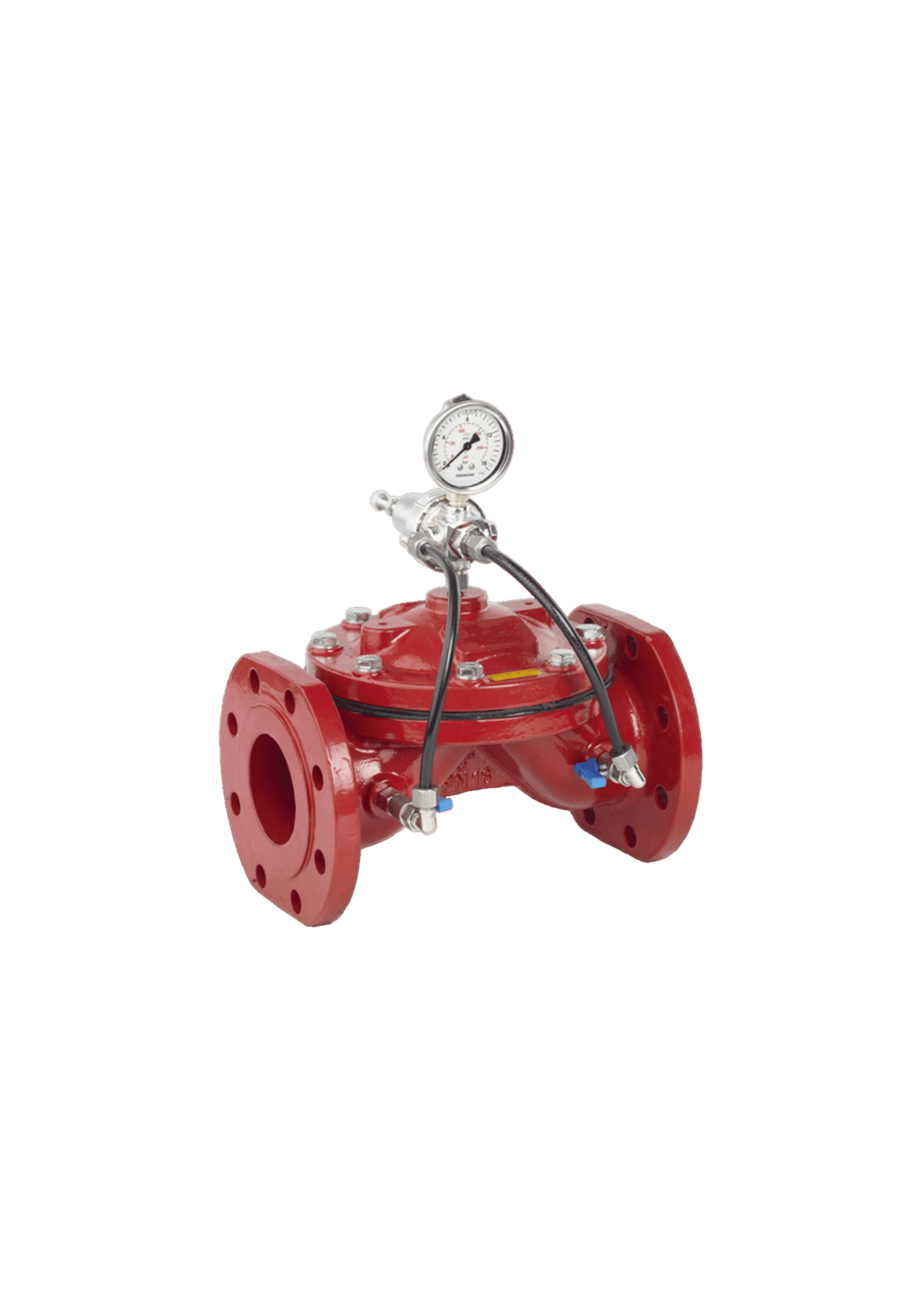
DCT12 Pressure Relief Control Valve
Devinsan offers proactive hydraulic safety solutions engineered for immediate, controlled dissipation of excess pressure and comprehensive protection against pipeline surge events. Designed for optimal network integrity and rapid response, these DCT12 Pressure Relief Control Valve units utilize pilot-operated mechanics to meet the critical demands of modern municipal pumping stations and high-pressure transmission mains.
Production Standard
Nominal Dimension (DN)
Nominal Pressure (PN)
Operating Temperature
Connection
Coating
Testing
DN 40 – DN 200
PN 6-PN 10-PN 16
-30° / +200°
EN 1092-2 ISO7005-2 Flanged
Electrostatic Powder Epoxy
TS EN 14384
Application Areas
The DCT12 Pressure Relief Control Valve is widely used across diverse industrial and commercial sectors, delivering reliable flow control and long‑lasting performance.
1. Water and Wastewater Systems
2. Chemical Industry
3. Food and Beverage Industry
4. Pharmaceutical Industry
5. Oil and Gas Industry
6. HVAC (Heating, Ventilation, Air Conditioning) Systems
In these applications, this type DCT12 Pressure Relief Control Valve ensures precise fluid control, maintains excellent sealing integrity, and supports efficient, safe operation even under demanding conditions.
The DCT12 Pressure Relief Control Valve is a highly specialized, hydraulically-operated valve specifically engineered to safeguard piping systems from dangerous over-pressurization and transient pressure surges (water hammer). Designed to meet the stringent demands of modern infrastructure, this valve automatically opens to discharge fluid when the system pressure exceeds a preset safety limit, ensuring consistent protection and minimizing the risk of pipe rupture.
At the core of the DCT12 Pressure Relief Control Valve is its diaphragm-actuated main valve, which operates based on the commands of a pilot system. The pilot mechanism constantly senses the system pressure and is set to open the main valve instantly when the pressure threshold is exceeded. This rapid, proactive response ensures that high-pressure peaks, typically caused by pump startup or sudden valve closure, are immediately neutralized, preventing catastrophic failures.
Manufactured from high-strength, corrosion-resistant materials (such as ductile iron) and built with a robust, angle or globe-style body, the DCT12 Pressure Relief Control Valve is designed to withstand continuous system pressure and severe dynamic forces during discharge. Its geometry facilitates smooth energy dissipation during relief, minimizing noise and vibration. The ability to precisely reset the relief pressure provides crucial control over network safety margins.
The DCT12 Pressure Relief Control Valve is ideally suited for applications immediately downstream of pump stations, at critical points on transmission mains, near rapid-closing valves, and anywhere that protection against hydraulic surge is essential for safety and structural longevity. Its superior rapid-response characteristics and dependable operation make it a preferred choice for engineers seeking a high-integrity, standards-compliant solution for long-term network protection.
In summary, the DCT12 Pressure Relief Control Valve offers an optimal combination of rapid surge response, precise over-pressure relief, and robust structural protection. With its pilot-operated design, durable construction, and focus on immediate safety, this unit stands as a trusted solution for modern fluid control and high-pressure system requirements worldwide.
1. General Information
The DCT12 Pressure Relief Control Valve is designed for the accurate, automatic relief of pressure to protect the upstream system. Proper installation, including securing the relief discharge path, is essential to guarantee safe operation and reliable protection.
2. Safety Precautions
Installation must be performed by qualified personnel only.
Ensure strict compliance with all local safety regulations and standards concerning working with pressurized pipelines and managing high-energy fluid discharge.
Wear appropriate personal protective equipment (PPE).
Confirm that the pipeline section is fully depressurized, isolated, and drained before attempting to install the DCT12 Pressure Relief Control Valve.
3. Pre-Installation Checklist
Inspect the DCT12 Pressure Relief Control Valve for any visible damage during transport or storage, paying attention to the main diaphragm housing and pilot tubing integrity.
Check that the valve type, size, and pressure rating match the system requirements and the required relief set point.
Verify that the valve interior and pilot line strainers are clean and free from debris.
Confirm that the mating pipeline flanges are properly aligned (parallel and concentric) and free from burrs or sharp edges.
Ensure the discharge pipe is securely supported and directed to a safe drain or reservoir.
4. Installation Procedure
Positioning: Install the DCT12 Pressure Relief Control Valve by connecting its inlet to the pressurized line (typically via a tee fitting) and its outlet to the discharge line.
The valve is typically installed with a dedicated isolation valve upstream for maintenance access.
Use the appropriate gaskets suitable for the medium and operating conditions.
Align the valve precisely with the pipe connection and insert bolts, tightening them gradually and crosswise in incremental steps.
Connect the pilot tubing securely and set the pilot mechanism to the designed maximum pressure threshold.
5. Post-Installation
Slowly reintroduce fluid and pressurize the system, checking immediately for leaks around the flange connections and the pilot tubing.
If leakage is detected, depressurize the system immediately and re-tighten the bolts or connections following the cross-pattern sequence.
Verify the pilot system adjustment and confirm the valve relieves pressure accurately when the set point is reached.
Record the installation details, relief set pressure, and final notes for documentation purposes.
Proper maintenance extends the service life of the DCT12 Pressure Relief Control Valve and ensures continuous, accurate system safety. Follow the guidelines below to maximize the longevity of this essential unit.
1. Routine Operation
Visually inspect the DCT12 Pressure Relief Control Valve exterior and pilot line tubing regularly (e.g., monthly) for signs of external leakage, vibration, or corrosion.
Monitor the system pressure closely to confirm the valve remains tightly closed at normal operating pressure and only relieves when the set point is exceeded.
2. Inspection Schedule
Monthly, check the pilot system strainers and filters (if present) for fouling and clean them to ensure accurate pressure sensing.
Quarterly, conduct a brief manual over-pressure test (if safe and possible) or cycle the valve to verify the main valve opens fully and closes tightly after relief.
Annually, perform a detailed internal inspection by removing the main cover to check the condition of the diaphragm, seating surface, and stem seals for wear or pitting.
3. Lubrication
The DCT12 Pressure Relief Control Valve typically utilizes fluid-lubricated internal parts (water).
External components or guides (if applicable) may require periodic lubrication; use only recommended grease types.
4. Seal and Gasket Replacement
Replace the main cover/diaphragm gasket and pilot tubing seals immediately if external leakage is observed.
The main valve seat and disc seals should be replaced if the valve fails to reseal properly after a relief event (i.e., it drips or flows continuously).
Always isolate the valve and fully depressurize and drain the line before attempting any maintenance work requiring cover removal.
5. Cleaning
Keep the exterior of the DCT12 Pressure Relief Control Valve clean to prevent surface corrosion.
If the valve is disassembled, clean all internal guiding surfaces and the pilot line components carefully to ensure precision hydraulic response.
6. Storage and Spare Parts
Store spare parts (diaphragms, pilot kits, gaskets) in a dry, clean, and cool environment, away from direct sunlight and temperature extremes.
Maintain a detailed record of all inspections, relief tests, and repairs performed on the DCT12 Pressure Relief Control Valve unit.
We prioritize quality at every stage of production to deliver durable, safe, and efficient products. Our continuous improvement and strict quality controls keep us at the forefront of the industry.
Our certifications prove our commitment to excellence and compliance with international standards, ensuring the safety and reliability of our products worldwide.
We continuously invest in innovation and quality to expand our certifications and meet evolving industry needs.

Frequently Asked Questions about the DCT12?
What are the main advantages of this valve?
The DCT12 Pressure Relief Control Valve provides an immediate and automatic safety outlet for over-pressure events, protecting the entire pipeline and connected equipment from catastrophic damage caused by sudden pressure surges or water hammer.
Why should I choose this product?
This valve delivers outstanding performance in both sealing and durability, making it a dependable choice for demanding applications. Its straightforward design facilitates easy installation, offering flexibility during system design. With a wide range of material options, it meets the needs of various infrastructure projects, from municipal water networks to industrial facilities.
What is the difference between a Pressure Reducing Valve and the DCT12 Pressure Relief Control Valve?
A Pressure Reducing Valve lowers pressure from a high inlet to a constant low outlet. The DCT12 Pressure Relief Control Valve maintains a constant maximum inlet pressure by opening only to vent fluid when that maximum is exceeded, protecting the system from spikes.
How is the relief set point determined and adjusted?
The relief set point is determined by the weakest component in the pipeline network. It is adjusted by modifying the spring tension or pressure setting on the external pilot valve, which controls the main valve opening pressure.
Where should the DCT12 Pressure Relief Control Valve be installed for surge protection?
It should be installed as close as possible to the point where the surge pressure originates, such as immediately downstream of a pump station or immediately upstream of a rapid-closing isolation valve, to quickly dissipate the surge energy.
Contact Devinsan
Reach out to our team for inquiries, quotes, and technical assistance